Object Model
Cube Model Definition
Some information about the conventions used for defining the cube model (see cube_model.hpp).
Note that while it is called “cube model” for historic reasons, other cuboids are supported as well.
Face and Corner Indices
The faces and corners of the cube are referenced by indices. The figure blow shows the positions of the faces (F0 to F5) and corners (C0 to C7) with respect to the cube reference frame.

When accessing elements of a list that corresponds to the faces (e.g. the list of face normal vectors), the i-th entry belongs to face “Fi”. Likewise for the corners.
There origin of the cube reference frame is at the centre of the cube.
Mapping Colours to Faces
The geometry of the cube is defined using only the generic face indices described above. In addition, there is a mapping of colour to face index. This way, it is relatively to adapt to new cubes where the order of colours are different (e.g. cube version 1 has a different colour order as cube version 2).
By convention the colour-to-face mapping is done such that the following colours are pointing in direction of the axes of the cube reference frame:
x: red
y: green
z: blue
Supported Object Versions
CUBE_V1-3
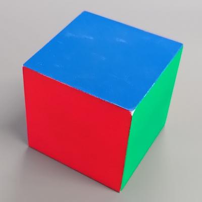
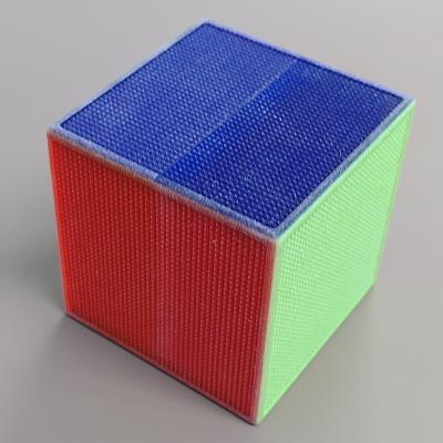
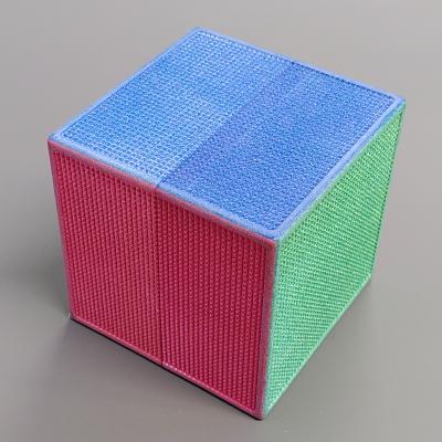
The cube versions 1 to 3 all have the same size (6.5 cm width). They were produced with different methods resulting in some differences on the colours and thus need different colour segmentation models.
Further v1 has a different colour-to-face mapping as the other two.
Note
v3 is not supported at the moment as the segmentation model for this cube has not been integrated into the software.
CUBOID_2x2x8
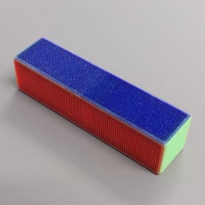
Cuboid of size 2x2x8 cm. Same manufacturing method as CUBE_V2, therefore the same colour segmentation can be used.