How to Build and Flash the Firmware
Get the Code
Simply clone the firmware repository (including submodules):
$ git clone --recursive https://github.com/open-dynamic-robot-initiative/udriver_firmware.git
The default configuration is assuming the Antigravity 4004 300kv motors. In
case you are using different motors, change the config_f28069m_drv8305
submodule to the appropriate branch.
Get MotorWare
Our software is based on Texas Instruments’ MotorWare library which can be
downloaded from their website. We made some modifications to the original
MotorWare which are needed to build our software.
We provide patch files motorware_1_01_00_18_patch with these changes, they
are included in the directories firmware_can/firmware_spi (note that
they differ for the two firmware versions.
Use the following steps to set up MotorWare for the project:
Download MotorWare v1.01.00.18 from the MotorWare website.
Install it to extract the source. For Linux users: Unfortunately TI only provides a Windows installer. There is not really an installation required, you only need the source files. You can get them by either installing on a Windows machine or using an emulator like Wine on Linux and then copy the files from the installation directory. Search for the directory containing the
swdirectory and copy it into the directoryfirmware_X/motorware(whereXis either “can” or “spi”, depending on which version you want to use). The structure should be like this:udriver_firmware/firmware ├── amd_motorware_ext ├── config_f28069m_drv8305 └── firmware_X ├── motorware <-- Add motorware here │ ├── docs │ ├── eclipse │ ├── mw_explorer │ └── sw └── mw_dual_motor_torque_ctrlFinally go into the
motorwaredirectory and apply the patch file:$ patch -p1 < ../motorware_1_01_00_18.patch
Install Code Composer Studio
To build the firmware and to flash it to the boards, you need Texas Instruments’ Code Composer Studio (CCS). These instructions are tested with version 9.1.0 but other versions may work as well.
When installing it, make sure the following components are selected:
Processor Support: C2000 32-bit Real-time MCUs
Debug Probes: TI XDS (this only needs to be selected explicitly in older versions of CCS)
When starting CCS for the first time, you have to specify a workspace location. Note that this “CCS workspace” is just where CCS stores its configuration and is not related to the location of the source code (i.e. the CCS workspace and the location of the firmware source code should be in different directories).
Build Instructions
Import in Code Composer Studio
Start Code Composer Studio and import the mw_dual_motor_torque_ctrl project
via the menu
Project > Import CCS Projects...
In the import dialogue, set the search-directory to the one of the
mw_dual_motor_torque_ctrl package. The Discovered projects pane should then
show dual_motor_torque_ctrl_X (X = “can” or “spi”).
Important
Make sure the “Copy projects into workspace” option is not set.
After importing, the project should show up in the Project Explorer.
Build and Run in Debug Mode
You can run the firmware in debug mode while the board is connected to the computer via USB. This is mostly useful for development.
Note: When using a TI LaunchPad board, make sure the boot switches are set such that jTag is enabled (see [below](#launchpad-boot-switches)).
Compile your code, using the “Release” build.
Make sure the board is powered and connected via USB to the PC. All three boot switche have to be in the upper position (see below).
Start the Debugger by clicking on the bug icon in the tool bar:

Enable Silicon Real-time Mode by clicking the corresponding button in the tool bar:

Run the code by pressing the Resume button:
 Now you can use a GUIComposer GUI or modify variables on the board via the
Expressions View.
Now you can use a GUIComposer GUI or modify variables on the board via the
Expressions View.To quit the debugger, press the Terminate button:
 Note: This will only detach the debugger, it will not stop the program on the
board!
Note: This will only detach the debugger, it will not stop the program on the
board!
With this procedure, the program is not permanently stored on the board. That means all steps have to be repeated, everytime the board is restarted.
Build and Write to Flash
To have the program written to flash rather than RAM (so that it is permanently stored on the board), simply switch the build type from “Release” to “Flash”.
Now compile and write the program to the board by running the debugger (same procedure like described above, only use “Flash” instead of “Release” build). You can use the debugger to run and monitor the program just like before.
Note that when using the TI LaunchPad, you have to set the boot switches on the board to the right configuration so that the firmware is automatically loaded from flash when restarting the board (see next section).
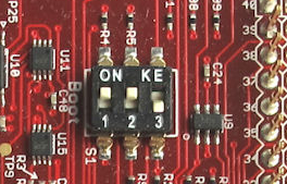
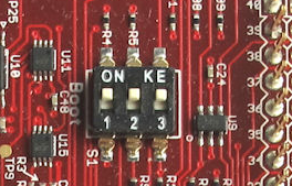
LaunchPad Boot Switches
This only applies to the TI LaunchPad board.
After the program is written to the flash memory with the steps described above, the boot settings have to be changed to tell the board to run the code in the flash rather than using the USB connection.
Change the switches on the board (hidden under the J1 BoosterPack…) to 1: Up, 2: Up, 3: Down.
Now the board should automatically run the program from flash when powered. Note that connection via USB is not possible in this configuration (i.e. to use the debugger or update the program you have to set the switches back to Up/Up/Up again).
Run firmware from flash |
Use jTag (to debug via USB) |
|
|