Important
The mw_dual_motor_torque_ctrl repository is not maintained anymore!
The CAN firmware has been integrated into the udriver_firmware repository and will be maintained there from now on. See the documentation of udriver_firmware for up-to-date installation and usage instructions.
How to Build and Flash the Firmware
Requirements and Paths
Requires the following additional repositories:
Further Texas Instrument’s MotorWare library is needed. There are modifications that have to be made to the original MotorWare in order to build this project. See the instructions on how to apply them, see the README of amd_motorware_ext.
By default, it is expected that all packages are in separate subdirectories of the same root directory. So your workspace structure should look like this:
workspace
├── amd_motorware_ext
├── mw_dual_motor_torque_ctrl
├── motorware
└── user_config_f28069m_drv8305
In case you cannot follow this structure for some reason, you can modify the
path variables $MW_INSTALL_DIR and $USER_CONFIG_DIR in the project settings
of mw_dual_motor_torque_ctrl.
Code Composer Studio
To build the firmware and to flash it to the boards, you need Texas Instruments’ Code Composer Studio (CCS). These instructions are tested with version 9.1.0 but other versions may work as well.
When installing it, make sure the following components are selected:
Processor Support: C2000 32-bit Real-time MCUs
Debug Probes: TI XDS
When starting CCS for the first time, you have to specify a workspace location. Note that this “CCS workspace” is just where CCS stores its configuration and is not related to the workspace directory that is described above (i.e. the CCS workspace doesn’t need to be in this directory).
Build Instructions
Import in Code Composer Studio
Start Code Composer Studio and import the mw_dual_motor_torque_ctrl project
via the menu
Project > Import CCS Projects...
In the import dialogue, set the search-directory to the one of the
mw_dual_motor_torque_ctrl package.The Discovered projects pane should then
show dual_motor_torque_ctrl.
Make sure the “Copy projects into workspace” option is *not* set.
After importing, the project should show up in the Project Explorer.
Build and Run in Debug Mode
You can run the firmware in debug mode while the board is connected to the computer via USB. This is mostly useful for development.
Note: When using a TI LaunchPad board, make sure the boot switches are set such that jTag is enabled (see [below](#launchpad-boot-switches)).
Compile your code, using the “Release” build.
Make sure the board is powered and connected via USB to the PC. All three boot switche have to be in the upper position (see below).
Start the Debugger by clicking on the bug icon in the tool bar:

Enable Silicon Real-time Mode by clicking the corresponding button in the tool bar:

Run the code by pressing the Resume button:
 Now you can use a GUIComposer GUI or modify variables on the board via the
Expressions View.
Now you can use a GUIComposer GUI or modify variables on the board via the
Expressions View.To quit the debugger, press the Terminate button:
 Note: This will only detach the debugger, it will not stop the program on the
board!
Note: This will only detach the debugger, it will not stop the program on the
board!
With this procedure, the program is not permanently stored on the board. That means all steps have to be repeated, everytime the board is restarted.
Build and Write to Flash
To have the program written to flash rather than RAM (so that it is permanently stored on the board), simply switch the build type from “Release” to “Flash”.
Now compile and write the program to the board by running the debugger (same procedure like described above, only use “Flash” instead of “Release” build). You can use the debugger to run and monitor the program just like before.
Note that when using the TI LaunchPad, you have to set the boot switches on the board to the right configuration so that the firmware is automatically loaded from flash when restarting the board (see next section).
LaunchPad Boot Switches
This only applies to the TI LaunchPad board.
After the program is written to the flash memory with the steps described above, the boot settings have to be changed to tell the board to run the code in the flash rather than using the USB connection.
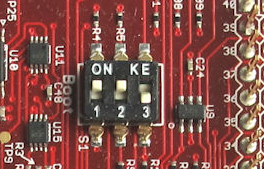
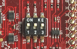
Change the switches on the board (hidden under the J1 BoosterPack…) to 1: Up, 2: Up, 3: Down.
Now the board should automatically run the program from flash when powered. Note that connection via USB is not possible in this configuration (i.e. to use the debugger or update the program you have to set the switches back to Up/Up/Up again).
Run firmware from flash |
Use jTag (to debug via USB) |
|
|